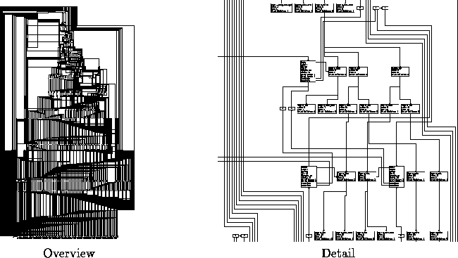
Figure 23: Data Structure Graph (858 Nodes, 1109 Edges)
The layer approach is mainly used to visualize the directed and the dense graphs that occur in compilers. The reason is the capability of the method to enforce uniform edge orientations and to avoid node overlappings. A compiler first parses the input program and checks the semantical rules of the programming language in a frontend. Usually, the intermediate program representation of the compiler frontend is a syntax tree annotated with attributes from the semantical analysis (e.g. types). Layout in layers produces good results for trees, where many simplifications of the algorithm can be done, e.g. partioning and crossing reduction for trees can be done simultaneously by only one depth first search traversal. The technical problem that annotations should occur as neighbors of the syntax nodes at the same level can be solved by combining neighbored nodes in phase 1 and 2 conceptually into one large node (Fig. 21). Fig. 22 shows a syntax tree annotated with two kinds of attributes: types and defined and used resources.
Typical compiler optimizations of the middle end use data flow analysis and work on procedure call graphs, annotated control flow graphs, or basic block graphs. The edges represent abstractions of the program flow. Together with various annotations such as data dependence edges, these graphs might become quite dense and complex. Control flow graphs are usually drawn with orthogonal edges (Fig. 14, left, Fig. 29). This convention comes from the flowchart diagram style of Nassi-Shneiderman.

Figure 23: Data Structure Graph (858 Nodes, 1109 Edges)
Data structure graphs show the details of the data structs used in the compiler. The nodes represent the structs containing several fields, and the edges visualize the pointers to the structs. Because pointers are related to certain fields, anchor point facilities are important, i.e. methods to specify the position of an edge port at a node. Because data structure graphs visualize many details, they are usually very large. Fig. 23 shows an example in overview and details.